Introduction to Radio
9 October 2007
Introduction
Wireless communication products, such as cell phones and satellite radio, have become as much a part of today’s everyday life as the microwave did two decades ago. During the next few years, this technology will spread from consumer products onto the shop floor. Automation and process engineers and managers need to understand wireless—or radio frequency (RF)—technology to properly assess and deploy the many wireless automation products that soon will become available to them.
Working with wireless products, which use the air as the medium of communication, offers challenges different from their more familiar wired product counterparts. Early incarnations of wireless automation products often left the buyer feeling mystified and shortchanged. They offered spotty performance and were difficult to install, configure and maintain.
Fortunately, the new generation of wireless products is easier to use. In addition to consuming much less power, these new products are easy to configure and install, offer built-in tools for monitoring the reliability of the wireless connection and can easily be integrated with existing wired infrastructure.
But before deploying an RF instrumentation control system in a facility, it is important to understand the basics of the technology, its advantages and its limitations. This white paper describes the major elements of a RF system and how they work together to move sensor data from point to point:
- Basic RF components
- Frequencies commonly used in RF product design
- Different modulation techniques for RF signals
- The effect of environment and interference on radio
- This white paper is the first in a series about wireless technology
The Basics of Radio Frequency Systems
All RF systems consist of two major elements: a transmitter and a receiver. As the names imply, a transmitter transmits a signal to a receiver, which listens for the signal.
The system includes a set of rules that define how the transmitter and receiver communicate. A rule set can simply specify that the transmitter must communicate with the receiver at a specific frequency. More complicated rule sets define not only the frequency, but the time when the transmitter and receiver communicate, how “loud” they can talk, the “language” they speak, and what to do if they can’t “hear” one another. Government regulatory agencies such as the Federal Communications Commission (FCC) set these rules, as do national and international standards groups such as the Institute of Electrical and Electronics Engineers (IEEE).
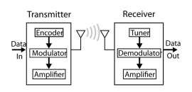 RF systems include a transmitter to send the radio signal and a receiver to receive it.
Problems with Early Designs
In early RF systems, a transmitter was connected to a sensor that transmitted information to a simple receiver. Early systems had a limited bandwidth—the range of frequencies they broadcast across and the amount of data transmitted in that band. Usually the data traveled on a single frequency, a system called narrowband.
Because of limitations in early integrated circuit (IC) technology, the transmitter could only transmit and the receiver could only receive. Without two-way communication, it was impossible to know if the receiver was receiving all the information the transmitter was sending.
Additionally, sometimes the receiver would not receive the signal, because signals can degrade, or attenuate, as they reflect off or pass through objects such as walls or filing cabinets. The RF system was unaware that the transmitted signal was lost, because the receiver was unable to acknowledge, or ACK, reception.
Because reliability was poor, those who tried these systems were generally disappointed and developed a jaded view of RF systems.
Improvements in RF System Design
As technology evolved, radio design saw major improvements in three key areas:
- IC technology. Both the transmitter and receiver were incorporated into a single component, called a transceiver. The transceiver makes it economical to implement bidirectional communications, dramatically improving reliability and maintainability.
- Higher frequency RF components. Because higher-frequency components generally operate across a wider RF band, they transmit more data than their lowfrequency counterparts. A drawback is that higher frequencies degrade—that is, they are absorbed—more readily as they pass through objects, which decreases range. To counter this effect, designers add amplifiers to the transmitter and design more sensitive receivers, increasing cost.
- Spread spectrum modulation. Modulation is the way data is impressed onto a radio wave. Today, many radio systems use a technique called spread spectrum to modulate data across the bandwidth of the radio. Spread spectrum allows multiple users to share the same frequency channel at the same time.
Two different spread spectrum technologies are commonly used today:
- Direct Sequence Spread Spectrum (DSSS) and Frequency Hopping Spread Spectrum (FHSS). Some hybrid schemes use both DSSS and FHSS. Another modulation scheme commonly used in ISM bands—those used for industry, science and medicine—is Orthogonal Frequency-Division Multiplexing
- (OFDM). Two newer spectrum-sharing modulation techniques are ultra wide band (UWB) and chirp modulation, both of which are gaining popularity.
For a description of the history of spread spectrum and the various types of spread spectrum, see the ISA’s tutorial “The Physics of Radio.”
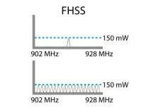 A narrowband signal occupies far fewer radio frequencies than a broadband signal.
Frequencies and Modulation
The first questions a product designer must consider when designing a product that uses an ISM radio system is what frequencies the product will use. The frequency should provide enough bandwidth to allow the data throughput rate to exceed the needs of the product—even with data-intensive applications—to enhance reliability and improve battery life.
The second question the designer typically considers is the type of modulation scheme to employ to impress data onto the broadcasted radio waves. Most designs today use some type of spread spectrum technology. For technologies such as WiFi that must transfer data rapidly, the IEEE has standardized DSSS technology. Because no such standard exists today for industrial sensing systems, today’s wireless sensing products all use a proprietary communication protocol.
The two most popular spread spectrum designs are Direct Sequence (DS) and Frequency Hopping (FH). DS and FH systems use this bandwidth very differently.
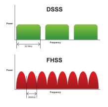 DS modulation spreads a lowlevel signal over a specific range of frequencies simultaneously. FH transmits a data signal over a different carrier frequency at different times, following a specific pattern.
Direct Sequence
In a DS system, the data to be transmitted, or input signal, is applied to a circuit, called a spreader, which uses software to apply a unique coding sequence to the data. The system spreads the data randomly across the bandwidth and outputs it to the air at a very low power level and at a particular time.
At the other end of the radio link, at essentially the same time, a receiver listens for low levels of signal and applies the same coding sequence to the data. If the data seem meaningful, the receiver processes it to the output of the transmitter. If the information is not meaningful, the receiver assumes it is noise and discards the information.
The unique coding sequence is the key element, because it enables many different DS systems to use the same frequency range without interfering with each other.
Frequency Hopping
In the FH system, the bandwidth is used differently. In these systems, the bandwidth is broken up into multiple smaller frequency bands or channels. The system breaks data to be transmitted into smaller chunks. The transmitter then broadcasts these chunks across the various channels in accordance with a unique pattern, known as the hop code pattern.
The receiver is synchronized with the transmitter and listens to the unique channels in the order of the hop code pattern. In this fashion, the data is reassembled and output from the RF system.
Managing the Airwaves with Communication Protocols
As technology allows us to build radio systems that operate across a wide range of frequencies and to have many users using the same frequencies, an obvious question arises: how do we manage access to this seemingly inexhaustible and invisible medium that is increasingly used for varying types of communications?
The government agencies that manage access to the RF spectrum in turn are advised by standard-setting associations such as the IEEE and special interest groups such as the Cellular Telecommunications & Internet Association (CTIA). In the US, the FCC has split and allocated frequencies in the RF spectrum for literally hundreds of different uses.
For example, ISM bands are allocated for industrial, scientific, and medical purposes. Each ISM band includes a range of frequencies. Europe’s International Telecommunication Union’s (ITU) 900 MHz band has a bandwidth of 26 MHz, from 902 to 928 MHz. The ITU’s 2.4 GHz band ranges from 2.4 to 2.5 GHz, and the 5.8GHz band ranges from 5.725-5.875 GHz.
Note that each GHz band is wider than 100 MHz.
When a modulation scheme is combined with the rules and regulations governing the use of a frequency band, the resultant method that transmitters and receivers use to talk to each other is referred to as the communications protocol.
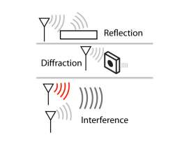 Multi-Path Fading is one cause of attenuation. Multi-path fading happens when radio signals reach the receiver through more than one path. In industrial settings, a received signal may include signals reflected off buildings, equipment, trees or the ground, as well as the line of sight signal.
The Effect of Environment and Interference
The Effect of Environment and Interference on Radio Wave Propagation
In a perfect world, with no interference, great radio designers, and a perfectly benign atmosphere, DS and FH systems work equally well. But the world is not perfect and interference does exist. Once we move outside of the lab and into the auto plants, steel mills, refineries, and cereal manufacturing facilities of the world, environmental factors—such as radio wave absorption and reflection—can significantly affect radio performance.
RF Link Quality Varies
The probability of reception at a given frequency on a particular channel at a particular moment varies. That’s why a cell phone connection can be dropped, even when both parties on the call are standing still. A dropped signal is referred to as radio link loss.
One way to address the problem is to vary, or hop, the frequency according to a predefined pattern. With frequency hopping, if interference on one frequency prevents a data packet from being received, the transmitter moves to the next frequency in the pattern and resends the data packet.
An alternative solution is to intentionally build multiple paths between the transmitter and receiver. This alternative is discussed in more detail in an upcoming white paper about networking.
Interferers Degrade Radio Performance
Interferers are objects that block radio signals or generate electrical interference. Interferers reflect, refract, or absorb radio signals, resulting in signal loss. Common interferers include objects, walls, ceilings, and other radios. As with the problem of radio link loss, frequency hopping can help stabilize the path.
Banner's Sure Cross System
For the Sure Cross system, Banner Engineering has developed offerings at both 900 MHz band and the 2.4 GHz band.
Banner chose the 900 MHz band because it offers long range and an inexpensive design, and the data throughput rate exceeds the needs of most expected sensing applications.
Banner also offers a 2.4 GHz design, because 900 MHz systems cannot be used in Europe or many parts of Asia, while 2.4 GHZ has broad worldwide acceptance. It offers higher bandwidth for data-intensive applications—in other words, it takes less time to transmit a smaller data packet, which can improve battery life. In addition, transceiver components are widely available.
Banner’s Sure Cross system uses frequency hopping to improve reliability. It splits the 900 MHz and 2.4 GHz bands into 27 unique channels. Sixteen unique pseudorandom hop patterns are defined across these 27 channels—the network ID determines which hop pattern code to use. Thirty-two different Banner Sure Cross systems can co-exist in the same physical space without interference: 16 at 900 MHz and 16 at 2.4 GHz.
Definitions
Featured Products
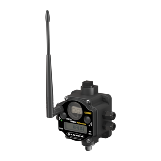
Performance Series Industrial Wireless Gateways and Nodes
Create point-to-multi point networks that distribute I/O over large areas. Input and output types include discrete (dry contact, PNP/NPN), analog (0 to 10 V dc, 0 to 20 mA), temperature (thermocouple and RTD), and pulse counter.