视频文本
大家好,我们是来自邦纳公司的 Scott 和 Darryl。在今天的培训中,我们要了解一些基本的光电概念。
在本模块中,我们将介绍光电结构和光电传感背后的一些基本原理。
Darryl,你能跟我们讲讲基本的光电知识吗?
当然可以。谢谢 Scott。那么,为什么要使用光电传感器而不是使用其他技术呢?
那是因为光电技术有很多优点。其一是非接触式,没有需要与目标接触的机械部件。
因此没有任何部件会磨损。光电传感器可以在许多不同的范围内检测许多目标,
不只是检测目标存在与否。现如今,我们的测量设备甚至可以测量目标与传感器之间的距离。
这在某些应用中非常重要。它可以进行毫米级的近距离检测,
也可以进行 700 英尺的远距离检测。另一个优点是使用寿命长。
所有光电传感器均采用固态和表面贴装设计,邦纳所有产品均属工业级产品。
这就是说,它们是为在恶劣环境下工作而设计的,适用于零下 40 摄氏度到 158 华氏度的任何场合。
它们可以承受很大的冲击和振动。而且速度非常快:一毫秒可以进行千分之一切片,一秒钟达到 1000 个切片。
而标准速度的传感器虽然可以在一毫秒的时间内工作,但只有一次切片。
邦纳传感器可以精确到 10 微秒。现在我们的时间缩短到了几百万分之一秒。
我们几乎可以检测任何目标,无论是箱子、汽车还是洗车场。
即使对于液体,光电传感器也能检测出大量目标。
就是这样,Scott。
那从构造的角度来看,这些光眼内部是如何工作的? 是因为有发射器和接收器,它们才能工作。
在下一张幻灯片中会详细介绍。太好了。是啊。
至于如何设置这些传感器,是否有不同的方法和模式?
当然。这确实取决于应用情况和传感器。在板上可以看到,有许多不同的外形尺寸。
根据应用的具体需求,它可以检测出你需要的传感器和设置方法。
太好了。谢谢 Darryl。现在总结一些基本的光电概念。
在光电传感器基本概念这一模块中,我们将简要介绍光电传感器的构造和工作原理。
Darryl,你能跟我们讲讲光眼的构造吗? 当然可以,Scott。
每个光电传感器都有一个发射器和一个接收器。
先从发射器开始。发射器是实际发光的装置,我们称之为 LED,代表发光二极管。
这些 LED 所做的实际上是脉冲处理。我们要为它们指定相应的频率。
另外还要将接收器调谐到发射器的频率。
为此可以联想一下收音机,它可以接收许多不同的电台。
但它只能接收收音机调到的电台。接收器也一样。
它只能接收到发射器的频率,因为这就是它所调谐的频率。
这样我们就能在工厂环境中阻隔大量噪音。
可见的红光很常见,红外线也很常见。
如果需要对比度,我们通常会使用可见的红光。
绿色和蓝色 LED 也可以帮助形成对比度,或者如果想帮助进行对准,想进行远距离对准,那可以使用红外线。
我们还有激光器,邦纳提供一级和二级激光器。二级的功率更大一些。
但你要知道,虽然邦纳也可以提供三级激光器,但不会去提供,因为它可能损害眼睛。
因此,如果您使用邦纳激光设备,那大可放心使用二级激光设备。
它不会对眼睛造成危害。Darryl,你谈到了调制这个词,也使用了电台的概念。
这是否能帮助我们避免受到顶灯和其他光源的干扰?
是这样吗? 正是如此,Scott。这是一种非常简单高效的传感器设计方法,可以忽略工厂中所有其他的光噪声。
我们的 LED 和激光传感器是否也能做到这一点? 我们的所有光电产品都能做到这一点。
没错。太好了。我这里有几个例子。有一些不同尺寸的光眼,比如 Q60。
可以看到,这里有一个非常大的发射器-接收器。一直到我们的 VS2(我们的超小型传感器),都是同样的概念。
无论你使用的是远距离、大功率还是近距离的小型设备,都是这样。
同样的概念也适用于发射器和接收器。然后使用 Darryl 所说的调制光。
现在这个模块将讨论如何应用这些传感器。
我们有很多不同的方法、不同的应用和不同的运行模式。
Darryl,你能介绍一下光电传感的不同模式吗?
当然可以,Scott。谢谢。
我们生产了很多种传感器。你可能想知道,如何为某种应用选择适合的传感器?
首先必须了解这些模式。我们会略微介绍一下。
先从对射模式开始。
对射模式由一个发射器和一个接收器组成,发射器位于单独的外壳中,接收器也有自己的外壳。
我们之所以从对射模式开始,是因为它能提供最多的过量增益。
稍后再谈过量增益。但一般来说,过量增益是指传感器发出的光能。
多多益善。因此,大家通常会希望从对射模式开始。
它的工作原理是,当物体进入发射器和接收器之间时,就会改变接收器的输出。
下一种模式是反射板式。
现在的这个发射器和接收器都在同一个外壳中,但还有一个叫做反射板的物体。
反射板会照射发射器和接收器元件。
当有物体进入它们之间时,接收器的输出就会改变。
这提供的过量增益是第二多的。从这里开始,我们将介绍接近模式,首先介绍漫反射型号。
漫反射型号同样只有一个外壳,内含发射器和接收器。
光线会向四面八方扩散,远处的目标就会将光线传回传感器,从而开启接收器输出。
在漫反射模式下,还会出现一种特殊的变化:固定场。
顾名思义,固定场只能看到固定的距离。
所以我们能够忽略背景。
在实际应用中,你可能需要检测工厂里的某个目标,但在它的正后方可能有一个闪亮的支架或一堵闪亮的墙。
固定场传感器可以忽略其正后方的物体。
与此类似,我们也有可调场。该距离并不固定。
可以调整。我们可以把它移进移出。显然,这也给我们带来了一些其他优势。
Scott,我们的模式就是这些。
这取决于你的环境是干净还是脏乱,也取决于你是否只需要检测某些东西存在与否。
又或者是必须确定与传感器的特定距离。
这有助于我们确定想要的检测模式。
在本模块中,我们将仔细研究对射模式检测以及与之相关的一些细微差别。
Darryl,能否给我们介绍一下对射模式检测? 当然。
谢谢 Scott。我们前面提过对射模式。
发射器自带外壳,接收器也自带外壳。
当一个目标出现在两者之间时,接收器就会触发输出,告诉你有一个目标。
在对射模式下,有一点需要注意,它们可以看到 700 英尺开外的远处,所以必须牢记电源问题。
这两个传感器都需要供电。但对射模式有个好处:它能提供最高的过量增益。
这些装置可以用于灰尘和/或碎屑较多的场合。
以洗车店为例,大量的水流、蒸汽、雾气和泡沫汹涌而下。
对射模式能够看穿这一切,非常可靠地检测出汽车。
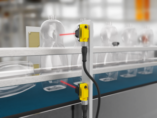
另一个快速应用是查看传送带上的盒子。
你想确保这些盒子出现在传送带上,对射模式可以非常有效地做到这一点。
此外,我们还使用了红色 LED、红外线、高功率 LED 和高精度激光。
同样,我们要对这些输出进行脉冲处理。现在还有一点需要注意,那就是输出模式。
有亮通操作和暗通操作。大家要明白这个概念。
如果发射器正对着接收器,就不会受阻。
传感器处于亮通操作模式。这表明传感器会正常输出,因为没有任何物体阻挡光线。
反过来,如果我们有一个暗通操作的传感器。
那么就只能在暗通模式下输出,即发射器和接收器之间有物体存在。
大体就是这样,Scott。Darryl,这么说来,光电传感器最基本的应用就是传送带上传送盒子。
那就亮通操作和暗通操作而言,如果我想在发射器和接收器的光束受阻时开启传感器的输出,会是哪一种呢?
是暗通操作,因为物体会阻挡发射器的光线,导致无法接收,也无法被接收器接收。
那如果我想看到盒子之间的缝隙呢?
那就是亮通操作。因为现在从发射器到接收器之间没有任何物体阻挡光线。
太好了。谢谢 Darryl。
过量增益是光电领域的一个术语。
我们需要知道我们可能拥有多大的能量。Darryl,你能谈谈为什么过量增益很重要吗?
特别是在选择适合应用的光电材料的时候?
当然。谢谢 Scott。正如 Scott 提到的,过量增益是指传感器发出的光能。
这一点非常重要。多多益善。对于每种应用,我们总会希望过量增益尽可能多。
这也是为什么我们总是从对射模式着手的原因。为了显示传感器的过量增益程度,我们来看一个过量增益图表。
这是一个对数对数图,简称 log log 图,可以显示过量增益。
看这个图表,在过量增益为 1 时,传感器才会开启。
增益超过 1 时,传感器会开启输出。
在所看到的这张图表中:20 米外的过量增益为 1。
这表明传感器可以看到目标,但只是勉强看到。
这就相当于我和你去看眼科医生,他们问:你能看到视力表上的最小对象是多少?
你也许能看到那张图表,但也只是勉强看到而已。这就是传感器在过量增益为 1 时看到目标的方式。
你肯定不会真的想在那里就进行操作。一般来说,如果是在工厂或仓库环境中,过量增益大致应该为 5。
如果环境稍脏,那就为 10。如果所处的环境非常非常脏,可能需要 50 的过量增益。
下面我们来举例说明如何使用过量增益图表。
假设我们是在一家工厂里,我们知道传感器上会积聚灰尘。
因此,尽管该传感器的视距可达 20 米,但我们可能不想在那么远的地方操作。
要达到过量增益 5,需要保持 10 米左右的距离。对。
顾名思义,过量增益就是超过开启所需的光量。
过量增益为 1 就能开启。但你并不总是想这样就工作。
如果应用环境稍脏,可能需要 10 的过量增益。
同样,虽然传感器可以看到 20 米外的地方,但你可能只想看到 6 或 7 米,以确保您能看穿灰尘和碎屑。
如果所处的环境非常脏乱,可能希望达到 50。
如果是这种情况,那么你就不要再退后三米了。
Scott,关于过量增益的知识就是这些。Darryl,这么说来,过量增益就是我们在应用中为了正常工作而需要达到的电能程度。
那我们为什么不在每种应用中都尽可能使用最高的过量增益呢?
因为在有些应用中你不会想用它。
例如,检测透明或半透明材料时,由于光能太强,可能会直接看穿。
Darryl,我们 QS30 系列中有些功率最高、过量增益最高的产品,就是很好的例子。
你可以看到,我的手可以穿过这些东西,而且不会跃迁。
输出需要两只手才能完成,这样对射模式传感器所含的电能就会直接穿过我的手。
因此,传感器可能有机会穿透所检测的产品。
这就是过量增益图表在每种应用中都非常重要的原因。
在接下来的模块中,我们将介绍与光电传感器有关的另外两个术语:光束模式和有效光束。
Darryl,在选择光电应用时,这两项为何如此重要?
这个问题问得好,Scott。我们先从光束模式开始。
光束模式就是辐射模式,或者说它显示了光如何从发射器发出,如何传播。
这一点很重要,因为在现实世界中,我们很多传感器都安装在传送带上。
它们需要彼此靠近安装,以便在传送带上跟踪产品时。
你需要知道光束模式的范围有多大,这样相邻的传感器才不会与另一个传感器产生交叉干扰。
这一点非常重要。我们在数据表中公布了这些数据。
来看这个例子。
最宽的地方(也就是零点)有发射器,它显示了光线的跨度。
可以看到,光线从零开始,最宽处是向上 25 英寸,向下 25 英寸。
因此,传播范围总共为 50 英寸。
这就说明:你要安装在另一个传感器旁边的传感器,中心与中心之间的距离不能超过 50 英寸。
这里有个例子。这是另一种视觉效果,可以看出,在光束传播模式内的任何地方,接收器都能接收到光线。
这是另一个例子,显示了光线传播范围总共为 50 英寸。
另一个重要术语是有效光束。它与光束模式不同。
有效光束保持不变,从不改变。
这是光束需要改变的部分,传感器才会切换输出。
我们要保持良好的工程实践。要 100% 遮挡接收器镜头,确保输出切换。
在我们展示的这个例子中,发射器和接收器之间有一个物体,是个大头针,但它并没有完全遮挡住光线。
因此即使那里有个目标物,接收器也绝不会知道,也不会切换输出。
我们在数据表中发布了这些信息。在本例中,有效光束为 13 毫米或半英寸。
这就是说,发射器和接收器之间的目标必须至少大于 13 毫米才能检测出来。
最后,我们要谈谈对射模式的优缺点。
其优点还是在于高增益。这样,检测范围就非常远。
它根本不关注颜色。其缺点是能力太强,可以穿透透明或半透明物体。
除非使用类似光圈的器件,否则很难看到小物体。
稍后我们会详细讨论这个问题。另外就是必须为两个传感器供电。
Scott,这方面的内容就是这些。
Darryl,你在介绍光电方面的信息时提到了一个词 - 串扰。
在处理对射模式的光电装置时,这可能是一个令人头疼的问题。
如何帮助我们消除可能遇到的串扰问题,你有什么建议吗?
这个问题问得好,而且确实经常出现。所以我提及了一下光圈。
光圈可以穿过接收器和/或发射器的镜头元件。
它限制了光图案,也限制了有效光束。
因此,它可以让光束辐射模式和有效光束变得更小,有助于消除串扰。
太好了。非常感谢 Darryl。
在应用光电装置时,反射板式检测有很多优势,而且非常灵活。
Darryl,能否谈谈在哪些地方可以使用反射板式,以及在使用反射板式光眼的解决方案时会有哪些细微差别?
当然可以,Scott。在反射板式下,有三种不同的类型:
标准、偏振和同轴。我们来一起回顾一下。
在反射板式下,发射器和接收器同在一个外壳中,由一块单独的反射板将光线传回接收器。
位于二者之间的物体会切换传感器的输出。
我们使用红光,红光有时很有用,因为可以在反射板式下用红光照射到 30 英尺或更远的地方。
它还有助于对准。我们还可以使用越来越流行的红外线激光。
偏振和同轴稍后再谈。
但在这三种不同类型的反射板式传感器中,标准传感器的检测距离最远。
不过,这也存在“坑”的问题。如果应用过程中有闪亮的物体,比方说食品厂里有闪亮的罐子正沿着传送带往下传送。那个闪亮的罐子可能会像反射板一样,发出错误的信号。
为了解决这个问题,我们可以极化。
但在此之前,先来谈谈这些设备的输出。就像对射模式一样,这里也有亮通和暗通操作。
简单回顾一下。亮通操作意味着发射器向接收器发送光线。
如果畅通无阻,传感器就会输出。暗通操作则恰恰相反。
如果发射器和接收器之间有物体,就会有输出。
这是大多数人使用反射板式传感器的通常模式。
极化可以用来帮助防止错误接近。我们的方法是:在发射器和接收器上各安装一个滤光片,相位相差 90 度。
我来举个例子。在这个例子中,发射器上的滤光片在垂直面上发出光线。
它会命中反射器以外的物体。以闪亮的罐子为例,
光线会在同一平面上返回。接收器上有一个水平镜头,这样光线就不会进入。
因此,要防止错误接近。当你用反射板做同样的事情时,光线会从垂直面射出。
反射板实际上会使光线失去方向感。从水平面返回的光线进入接收器,我们就能进行检测。
但这样做有一个缺点。由于使用了滤光片,过量增益较少,因此范围也较小,但不会产生错误接近。
这些反射板式传感器都有盲区。
这是因为:当光线离开发射器,射到反射器中的角立方体时,角立方体会试图将光线送回同一平面。
但随着时间的推移,它会逐渐分散开来。传感器和反射板之间必须保持一点距离。
这可能是一个缺点,取决于具体的应用。
另一个重要部分是有效光束。在本例中,有效光束就是反射板的大小。
如果你在应用过程中要查看一个小物体,比方说一枚大头针。
它不会挡住整个反射板。所以传感器可能永远看不到这枚大头针。
要解决这个问题,就必须使用较小的反射板。但请记住,反射板越小,表面积越小,射程就越短。
最后是同轴。每个传感器、每个发射器都自带镜头。同样,接收器也是如此。
在同轴模式下,它们使用分光镜和滤光片共享同一个镜头。
光线射到分光镜上,反射到反射器,然后再射回来。
分光镜的一部分将光线传送到接收器。这给我们带来了很多优势。
我们不再有盲区。有了这项技术,我们就能看到透明物体。
最后,总结一下优点:反射板式的过量增益负荷量位居第二。
你只需要启动一个站点。如果使用同轴传感器,就不会有盲区。
这也提供了非常紧密的光束,可以用来观察小开口或进行精确的前沿检测。
我们可以检测出透明物体。Scott,就是这些。
Darryl,你刚才提到的反射板,就是指硬角立方体反射器,就像这里的这个人一样。
另一个选择是反光胶带。它非常灵活。
可以进行修剪。可以把它剪下来,剥掉背面,粘在栏杆上。
它在这方面非常灵活。
不过,能否举些例子说明你不想使用反光胶带,以及这样做的一些弊端?
好。问得好。胶带深受许多客户的欢迎,虽然它可能并无优势。
主要原因是:每个反射板都有角立方体。
这就是将光线送回传感器的原理。
有了胶带,就有了不同类型的角立方体。它们的效率不如硬壳反射板。
但如果使用反光胶带,就会损失不少量程。
在使用偏振传感器时,这也会造成问题,因为角立方体和胶带不能像硬壳反射板那样旋转光线。
邦纳公司现在确实提供这方面的专用胶带。大家可以致电我们公司的应用工程师,他们会帮助解决这个问题。
虽然胶带使用灵活,但在反射板应用中,有时硬盒反射板是一种更好、更可靠的解决方案。
而胶带可能更多用于那些成排的应用。
光电感应接近模式包含了许多不同的应用解决方案,
无论你是想确定目标存在与否,还是想确定距离并忽略一些背景,都有适合的解决方案。
Darryl,你能否介绍一下接近模式的不同选项,在我们应用光眼时,应该注意哪些方面的事项?
当然可以,Scott。我们从漫反射模式开始。漫反射模式传感器的发射器和接收器共用一个外壳。
不需要在另一侧安装反射器或接收器之类的东西。
漫反射可以将光线散开。而它要检测的物体就是将光线传回元件的物体。
同样,在这些传感器中,我们使用了红色 LED、红外线和激光。
使用漫反射传感器时需要注意一点。
我们所有的传感器都有规格范围,这个范围是以目标为基础的,目标会将 90% 的光反射回来。
在现实世界中,情况并非总是如此。因此,尽管传感器的规格范围可能有三英尺,
但如果它看到的目标较暗,那么它只能检测出一英尺范围内的目标。
这是所有漫反射传感器的普遍问题。这一点需要注意。
此外,漫反射传感器没有截止距离。
如果需要检测传送带上的盒子,但盒子后面有闪亮的物体,那么它可能会看到盒子和闪亮的物体。
但漫反射的优点是成本很低,在非常简单的应用中效果也很好。
现在有一种方法可以解决这个背景问题。我们可以采用漫反射的变化形式。
到目前为止,每个传感器都只有一个发射器和一个接收器。
而我们的固定场传感器有一个发射器和两个接收器。
第二个接收器可以截断,因为我们使用的是三角测量法。
在这个例子中,你会看到光线从发射器发射出来,命中目标。
目标越近,攻击角度越大,它就会命中一号接收器。
只要光线命中接收器 1,它就会输出。
但可以注意到一点,当目标后退时,角度发生了变化,最终命中了二号接收器。任何光线照射到二号接收器都会关闭输出。
在这种情况下,如果我们有固定的范围,就能清楚地知道这个范围在哪里结束。
因此,目标后面就算有闪亮的支架,固定场传感器也会予以忽略。这是一种很大的优势。
这是命中二号接收器的另一个例子。
我们还可以使用可调场,可以调节,不再固定。
你可以将它调到自己需要的范围,继续获得背景抑制。
这是另一大优势。
使用漫反射和固定场的优势还有:只需为一侧供电;降低安装成本。
它可以检测出设定距离外的物体,忽略背景中你不想看到的物体。
有了背景和可调场传感器,颜色检测也不成问题了。
Darryl,在接近模式下...如果需要获取经过的产品上的注册标记,哪种模式最合适?
固定场可能会非常适合,这要取决于不同的应用。
因为当注册标记经过以后,你可能会有一些不会被忽视的背景。
或者使用可调场,这样就能更精确地确定需要截断的位置。好的。
然后是与接近模式相关的亮通操作和暗通操作。
如果我们想在目标出现在我们面前时,将输出转换为开启模式,应该采用哪种模式?
应该采用亮通模式。原因在于,当光线离开发射器时,它所寻找的目标会将光线传回。
当传感器看到光线时,它就会开启输出。
所以说,暗通操作是针对没有目标存在的情况,对吗?
没错。好的。非常感谢 Darryl。
光纤传感器提供了一种独特的方式和更高的应用灵活性,其应用范围不仅限于简单的光电传感器。
Darryl,你能否介绍一下在应用中何时何地应使用光纤传感器的一些基本要素?
当然可以,Scott。问得好。好。有时候,环境决定了唯一的选择就是光纤传感器。
正如你在这里看到的,我们有很多光电传感器,但其中一些可能不够小,无法进入非常狭小的密闭区域。
这正是光纤传感器的优势所在。
它们的工作原理是,有一个光纤放大器,还有一根玻璃光纤或塑料光纤连接到放大器。
光纤将光线发送到检测区域,然后返回放大器。
这样做有很多好处。同样,你可以看到一小块区域。
刚才我提到,我们有一个响应速度为 10 微秒的光纤放大器。
这就是我们的光纤系列。
但另一大优势是,由于纤维没有电子元件,因此可以进入电噪声非常大的环境以及化学环境。
有时,它们甚至可以进入存在有害气体的危险环境,这些地方不能有任何电子设备,因为可能会发生爆炸。
因此,它的优势非常多。下面我们来仔细了解一下玻璃光纤和塑料光纤。
为什么要用玻璃光纤? 玻璃光纤耐受高达华氏 900 度的温度。
由于它采用玻璃和不锈钢材质,因此可以抵御很多化学物质。
它的缺点是:由于是玻璃材质,所以柔性不是很高。可能会出现断裂。
塑料光纤的尺寸稍小一些,所以一般不会像玻璃光纤那么大。
虽然我们现在有了高功率放大器,但由于它们的功率很高,所以也能提供这个范围。
你还可以在塑料光纤上铺上一层不锈钢板。
而且它们非常灵活。Scott,这方面的内容就是这些。
Darryl,假如我们的应用是拾取和放置机器。
也许机器人末端效应器会经常移动。
我们是用玻璃光纤、不锈钢护套光纤,还是用更小一点的塑料光纤?
我们做出这种选择的理由是什么?? 这个问题问得好。
简单说来,应该选择塑料光纤。好的。
原因你看到了,它非常灵活。这样的话,机械臂就算大幅弯曲也不会断裂。
它有坚固的塑料内芯。因此,与有大量多股玻璃的玻璃光纤相比,它不太会断裂。
不过持续弯曲会削弱这一点,最终会失效。
因此,在这些高柔性应用中,塑料光纤是最佳选择。确实。
好的。非常感谢 Darryl。任何光电传感应用的目标都是向外部控制器提供输出。
但这些输出类型也会让人有点费解,在这方面也有很多因素需要考虑。
Darryl,你能介绍一下光电传感器的输出方式吗?
没问题。在离散量输出方面,有两种选择:PNP 源型或 NPN 漏型。
先从 PNP 开始。顾名思义,“源型”就是电压源。
在我们现在看到的图像中,可以看到传感器已通电。
正极在 1 号引脚上,接地在 3 号引脚上。沿着这条线,四号和二号引脚就是输出端。
在这种常闭触点配置中,我们向负载发送正电压。
现在负载可能是 PLC,也可能是 HMI。可能是继电器,
也可能是许多不同的项目。在负载的另一端,它必须回到地面,来构成电流路径。
那么,你会使用哪一种呢? 如何判断是使用 PNP 还是 NPN?
这由 PLC 决定。
例如,如果使用 PLC,那么相应的卡会确定它希望获得的是源型输入还是漏型输入。
NPN 所做的恰恰相反,它获得漏型输入。在这个例子中,如果你看三号引脚,可以看到直流接地。
继续顺着路径找到二号引脚,那里就是负载的位置。
我们发送一个漏型输入。负载的另一端是正电压。再次构成电流路径以开启输出。
还有另一种选择。我们有几个带有继电器输出的传感器。
什么时候使用? 在哪些情况下使用? 你需要切换交流电源。
继电器的优点是可以切换交流或直流。
在这种情况下,我们可以为传感器供电,因为这是一种通用电源;它可以由交流或直流供电。
你可以使用直流电源为传感器供电,也可以切换到交流电源。
这是一项很大的优势,取决于你的输出需要怎样的电源。那么 Darryl,NPN、PNP 都是固态输出,对吗?
对的。你现在展示的是实际界面。
这显然是一个机械干触点。
与 NPN 或 PNP 的固态输出相比,真正的输出有什么缺点?
我们之前谈到过响应速度。我们的传感器速度极快,最快可达 10 微秒。
继电器不会有这样的响应速度。它们的速度要慢得多。
在当前情况下,它们可以进行大电流开关。很大的电流。但缺点是速度较慢,一般在 20 毫秒左右。
如果你的应用速度较快,它可能无法满足你的需求。耐用性如何?
非常耐用,因为它是机械装置。这些触点可以承受非常之多的接通和断开动作。
最终会有磨损。数据表中说明了这一点。太好了。
好的。感谢收看我们的光电传感模块。
我们介绍了有关对射模式、反射板式、接近模式以及相应的输出方式的基础知识。
我们是 Darryl Harrell 和 Scott Behnke。非常感谢。